
CANE CRUSHER MILLS

4,20,000

CANE CRUSHERS AND MILL TANDEMS

Application

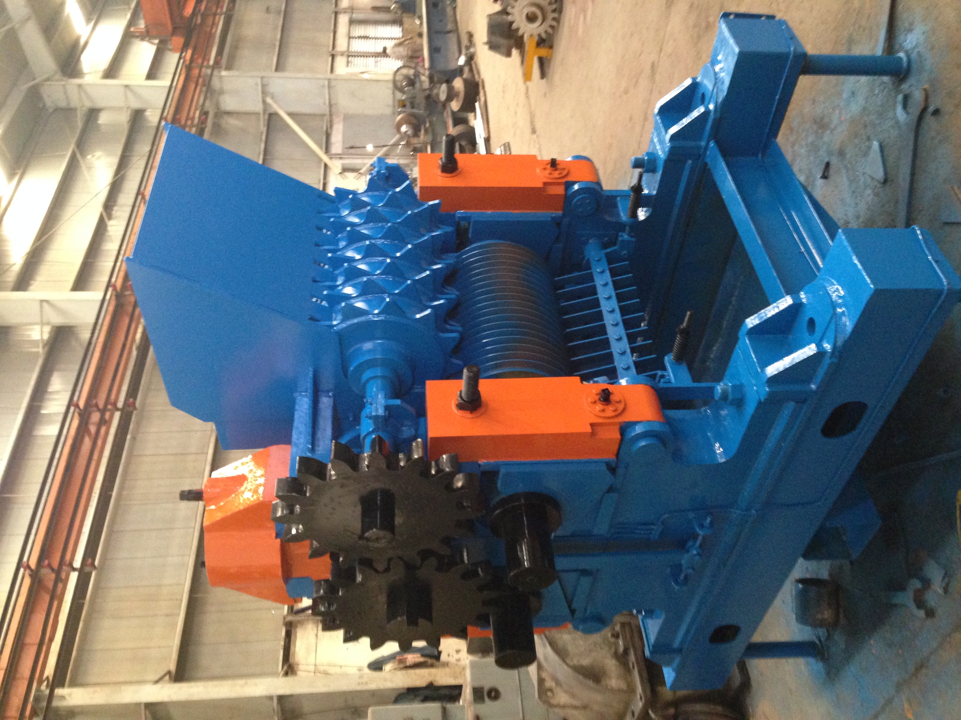
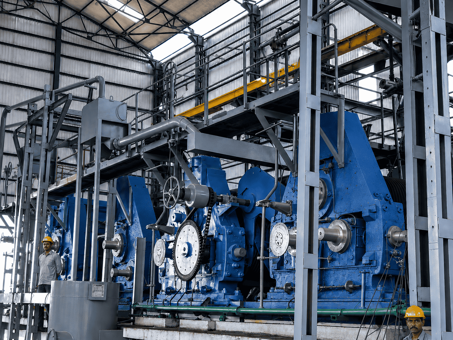
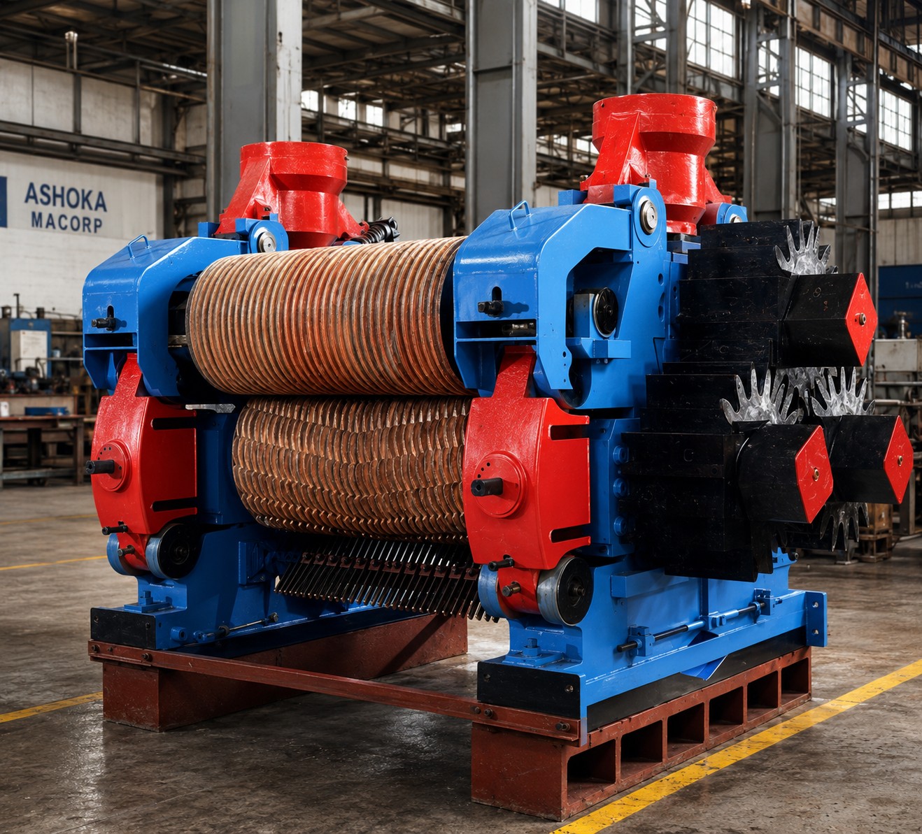
Cane crusher mills are used for extraction of juice from cane by a stage wise crushing action using a series of suitably designed grooved rollers in a crushing mill. The cane is fed between the rollers to facilitate its crushing and thereby extraction of juice for further processing. A series of individual mills are put together to form a milling tandem depending upon the capacity and efficiency of extraction and based on which the most suitable size of the rollers are selected.

Working Principal

The cane stalks are fed to the main cane carrier from where it passes through a series of cane cutters (generally two- cutter I & II) to chop the cane into fibers. This then passes through a fiberizer which shreds the cane into fine fibers & drops these fine fibers to a below placed belt conveyor from where it is carried to the feed rake carrier. This carrier then conveys the fine chopped cane fibers to the first mill through its donnelly chute placed before the first mill. After passing through the first mill the bagasse passes to the subsequent mills for further juice extraction through a series of inter rake carriers & donnelly chute’s. The final bagasse after the last mill is then discharged to a suitable bagasse carrier for further use as boiler fuel, cattle feed etc.

GENERAL DESIGN FEATURES

Mill Rollers

A crusher mill can be made in number of configurations depending upon the number of rollers. A three roller mill which was generally used in yesteryears has now been converted into a four roller, five roller and six roller mill. Most common of all still being a four roller mill. Rollers are made up of hard course grain cast iron shells shrunk fitted on forged alloy steel shaft with square ends. All the top rollers shall have cross type coupling end. The rollers are provided with circumferential v-grooving (radial grooving) for effective and continuous crushing action. Each roller shall be fitted with cast steel crown pinion for transmission of power from the gear reducer. A typical four roller mill has an under feed pusher roller for higher extraction by a pushing action of cane against the rollers. The under feed pusher roller is driven by the top roller through gears to maintain a surface speed of about 10% higher than the mill roller surface speed.

Head Stock, Top/Side Caps

Head stock are of king boltless type design, fabricated from tested mild steel IS 2062 plates duly stress relieved. Head stocks are mounted on the base frame provided with the mill. Top and side caps shall be of cast steel as per graded IS: 1030 casting. Top caps embrace the mill housing and this gives additional strength against any lateral thrust of the top bearing with two bolts which are only for securing the cap in its working position.

Mill Hydraulic System

Each mill is provided with a hydraulic system consisting of hydro pneumatic accumulators, one for each of the journal of the top rollers. In order to know the roller movement an indicator either electronic type of liquid magnification type is provided. The hydraulic system is suitably designed for sufficient working oil pressure. One forced feed oil lubricator for each mill having various points is provided so as to have proper distribution of lubricant at all necessary locations including each bearing.

Mill Drive

Mill drive is to be directly coupled through a flexible gear coupling to a planetary gear reducer capable of transmitting the desired power continuously under shock load conditions at full rated speed of the motor. The operating speed of mill rollers is generally reduced to an output rotation of about 7 RPM through a set of pinions mounted on the each mill roller. The pinions shall have special crown type module of appropriate size of which the teeth would be machine hob cut using specialized hobbing machines. Suitable bed plates made in sections and mild steel guards for enclosing the open pinions is provided. Proper provision to lubricate the gear reducer as well as the pinions is also provided. The mill top roller shall be connected to the transmission pinion shaft by means of a tail bar through a square coupling. Two cast steel couplings, one of lesser cross section so as to act as a fuse to safeguard the reduction gearing units is also provided.

Project Range

Technical Data Table for Hydraulic Cane Crusher :

Model Size of Roller in the Mill
(Dia x Length x No. of Roller)
Inch x Inch x No.
Capacity of Cane Crushing
(Tons per Hour)
Power Required (HP)
AMTC-11-14-6
11 X 14 X 6 Roller
4.5
75
AMTC-12-14-9
12 X 14 X 9 Roller
5
115
AMTC-13-18-6
13 X 18 X 6 Roller
7.5
100
AMTC-14-21-9
14 X 21 X 9 Roller
10
160
AMTC-16-24-6
16 X 24 X 6 Roller
15
135
AMTC-16-24-9
16 X 24 X 9 Roller
20
210
AMTC-18-30-9
18 X 30 X 9 Roller
25
280
AMTC-16-24-12 +FB
16X24X 12 Roller with Fibrizer
25
800
AMTC-18-30-12 +FB
18X30X 12 Roller with Fibrizer
38
1080
AMTC-20-40-12 +FB
20X40X 12 Roller with Fibrizer
50
1500
AMTC-24-40-15 +FB
20X40X 15 Roller with Fibrizer
75
2500

FOUR ROLLER MILLS

Design Features

• Robust heavy-duty housing design for improved rigidity and stability to handle higher throughput.
• The pin-type construction makes it easy to assemble or dismantle. The side caps provide a platform for rapid emergency maintenance.
• The fourth roller rests directly on the main housing and is provided with bolting and locking arrangement to allow close setting.
• The drive to the fourth roller is directly from the top roller through heavy and long teeth pinions.
• Vertical and horizontal adjustments are made possible by machined packing plates and specially designed bearing housings.
• Most suitable for cane feed with vertical donnelley chute.

Basic Advantages

• Higher capacity with no extraction loss
• No mill-gripping problems even with too fine a preparation, higher imbibition rates up to 300% with high temperature.
• Ease in setting adjustments, assembling and dismantling, due to the unique simplicity of design.

FIVE ROLLER MILLS

Design Features

• Easily adaptable on conventional three roller mills
• Hinged housing for easy maintenance without disturbing the original alignment
• Common static collar with mill, with stainless steel linings, providing efficient side juice drainage.
• Pressure chute in heavy construction with stainless steel lining, specially designed for smooth flow
• Toothed roller hard-faced all over for better gripping and longer life
• Drive from the main rollers / separate drive as per the power requirement .

Basic Advantages

• Increase in capacity by about 25 percent over conventional mill with no loss of extraction
• Higher crushing rates achieved at lower mill speeds, improving the gripping and reducing the re-absorption
• Reduction in installed mill power per TFH

Frequently Asked Questions

We primarily serve the oil & gas, energy, and resource extraction industries. Our expertise spans exploration, offshore drilling, processing management, and asset maintenance, making us a comprehensive partner for end-to-end operations.

We follow strict international safety standards, implement advanced monitoring systems, and conduct regular risk assessments. Our teams are trained in emergency response and operational best practices to ensure safe and efficient drilling in complex environments.

We utilize modern tools such as seismic imaging, geological modeling, and data analytics to assess site viability and resource potential. These technologies help us make informed decisions and optimize development strategies.

We enhance efficiency by optimizing system design, integrating automation, and continuously monitoring performance. This allows us to increase output, reduce waste, and maintain consistent product quality while adhering to safety standards.

Our services include preventive and predictive maintenance, real-time equipment monitoring, inspections, and lifecycle management. These measures help reduce downtime, extend asset life, and ensure reliable long-term operations.